Analogs for 3D printed implant models

Jo Chen

Jo Chen

Well-Known Member
Full Member
Messages
537
Reaction score
105
Bob
True, that technique does not work for a screw retained case. Yes, there has been a resurgence in SR cases but I see more than 50% of cases still cementable when I visit labs.
Rkm
Yes you can McGyver an analog in to a printed or milled model as alluded to by cnhart. Make a seating jig over the scan body and the adjacent teeth. Remove the incorporated scan body and create a hole in the model for the analog. Now take a real scan body of the same type and attach an analog. Utilize the seating jig to reposition the scan body-analog assembly back on to the model and bond the analog in place with light cure material.
Have done this a couple of times for Biohorizons cases with the 3in1 abutment as the scan body. Worked like a charm.
 
rkm rdt

rkm rdt

Well-Known Member
Full Member
Messages
21,447
Reaction score
3,288
Bob
True, that technique does not work for a screw retained case. Yes, there has been a resurgence in SR cases but I see more than 50% of cases still cementable when I visit labs.
Rkm
Yes you can McGyver an analog in to a printed or milled model as alluded to by cnhart. Make a seating jig over the scan body and the adjacent teeth. Remove the incorporated scan body and create a hole in the model for the analog. Now take a real scan body of the same type and attach an analog. Utilize the seating jig to reposition the scan body-analog assembly back on to the model and bond the analog in place with light cure material.
Have done this a couple of times for Biohorizons cases with the 3in1 abutment as the scan body. Worked like a charm.

Hear that Bob? I'm not out to lunch after all;)

Thanks Jo.
 
BobCDT

BobCDT

Well-Known Member
Full Member
Messages
2,870
Reaction score
521
Here we go. We're talking digital impressions and digital models for implants. This is an automated workflow. any automated workflow should either save time or money or both. This "McGyver" approach definitely does not fit that bill. But, I agree it could be done and probably would work well for single units. However, longer term, we need a solution that is faster and or cheaper using printed and milled models.
 
rkm rdt

rkm rdt

Well-Known Member
Full Member
Messages
21,447
Reaction score
3,288
Well you're still going to have to insert an analog into the model somehow.

So how do you do it?
 
Jo Chen

Jo Chen

Well-Known Member
Full Member
Messages
537
Reaction score
105
Here we go. We're talking digital impressions and digital models for implants. This is an automated workflow. any automated workflow should either save time or money or both. This "McGyver" approach definitely does not fit that bill. But, I agree it could be done and probably would work well for single units. However, longer term, we need a solution that is faster and or cheaper using printed and milled models.
Until we have a solution for this; McGyver or accept only Straumann cases. :)
 
cadfan

cadfan

Well-Known Member
Full Member
Messages
1,524
Reaction score
207
3d printed models with stainless steel analogs


Hi Lance-
Thanks for the picture of the analog with the flat bottom.
Has anyone figured out a way to use a standard analog in a 3d printed model by either having it printed where the pieces split down the middle of the implant site to insert the analog.
I have the stl library files that we give away for exocad, 3shape, and dental wings and our analogs have a flat side at the bottom of it so I am starting to talk to the stratsys /objets and other printer manuf to figure out a solution.

I think it would be tough to bring in an analog from the bottom of the model and orientate it properly.
Any input on possible workarounds and options I would like to know since my customers are dental labs asking me for this solution and there are plenty of labs that are tired of being locked into using a milliing center for this proprietary solutions and want options.

thanks
Keith Goldstein
DESS USA
DESS-USA | Dental Implants & Restorative Prosthetics
[email protected]
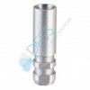
dess-usa_active_hex_analog_14041.jpg
Block out the retetions viritual create a little offset on the cylinder and use the flat parts as rotationsecure maybe although with a little offset put it as a placeholder on the scanabutment and print the modell place the original in the model maybe with a special peace to press into the printed model.Depending on the accuracy of the analogs . scanbodys and printers create the offset. Ill think for single units it works very fast.For splinted multi units ill think you can only match a digital part into a analog part .
 
BobCDT

BobCDT

Well-Known Member
Full Member
Messages
2,870
Reaction score
521
I believe standard analogs will need a redesign to facilated digital models.
 
rkm rdt

rkm rdt

Well-Known Member
Full Member
Messages
21,447
Reaction score
3,288
I believe standard analogs will need a redesign to facilated digital models.

If that's the case then they could be designed to be removable from the model.

It would have to be a tapered design similar to a brass dowel pin.

It would be nice to have an exact copy of the implant to use.

I think the fabrication cost would be too high though.
 
BobCDT

BobCDT

Well-Known Member
Full Member
Messages
2,870
Reaction score
521
I don't think the exterior of the analog would need to be shaped like an implant. The geometry would simply need a vertical and rotational stops.
 
rkm rdt

rkm rdt

Well-Known Member
Full Member
Messages
21,447
Reaction score
3,288
I don't think the exterior of the analog would need to be shaped like an implant. The geometry would simply need a vertical and rotational stops.

Like a dowel pin?
 
BobCDT

BobCDT

Well-Known Member
Full Member
Messages
2,870
Reaction score
521
Like a dowel pin?
No, a dowel pin will not work due to the taper. The taper will result in some potential error in the vertical location of the analog. There will need to be a shoulder to act as an exact vertical stop built into the design.
 
rkm rdt

rkm rdt

Well-Known Member
Full Member
Messages
21,447
Reaction score
3,288
I think the only vertical stop design that would work properly would be a collar .

The diameter couldn't exceed the diameter of the platform though.
You could still have the taper below the collar.
 
JohnWilson

JohnWilson

Well-Known Member
Full Member
Messages
5,487
Reaction score
1,575
I know nothing about printing, however, Seems like an easy way would be to have the software see the long access of the fixture based on the scan body. Perhaps the digital model could be then oriented via software to line up to the build plate on a 90* angle to the base of the fixture. The build plate would have a jig to insert standard analogs that the software would reference and then the model would be printed around the analog.

Seems easy :), ok pay me the money!
 
rkm rdt

rkm rdt

Well-Known Member
Full Member
Messages
21,447
Reaction score
3,288
I know nothing about printing, however, Seems like an easy way would be to have the software see the long access of the fixture based on the scan body. Perhaps the digital model could be then oriented via software to line up to the build plate on a 90* angle to the base of the fixture. The build plate would have a jig to insert standard analogs that the software would reference and then the model would be printed around the analog.

Seems easy :), ok pay me the money!

That's basically the same thought I had with the transfer jig concept

I think printing a socket to receive a standard analog would be the simplest solution.
Custom analogs would be proprietory.
 
TheLabGuy

TheLabGuy

Just a Member
Full Member
Messages
6,249
Reaction score
817
Call 3i-Biomet and ask them to give up the goods on how they do the Encode...lol
 
cnhart@me.com

[email protected]

Active Member
Full Member
Messages
170
Reaction score
16
Stock analogs do not always have the internal anti rotation in alignment with outer due to the nature of the broaching process which is arbitrary
 
Top Bottom