Medit/exocad Pains

RileyS

RileyS

Well-Known Member
Full Member
Messages
2,868
Reaction score
461
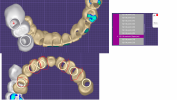
Anyone know why this warning keeps popping up when trying set the connectors and finalize the case? Usually I can add or subtract from contacts and that works. Not this time, I keep getting this error.

1634332608535.png
 
J

Josh Claxton

Member
Full Member
Messages
25
Reaction score
0
Heya Riley! Looks like you might have used the + sign for connectors. Usually this works great, but occasionally with overlapping pieces, etc, the software has a hard time connecting. In instances like this use a shape for the connector, then once the bridge is merged you can freeform it to thicken it up to the desired amount, or thin out the connector
 
RileyS

RileyS

Well-Known Member
Full Member
Messages
2,868
Reaction score
461
Heya Riley! Looks like you might have used the + sign for connectors. Usually this works great, but occasionally with overlapping pieces, etc, the software has a hard time connecting. In instances like this use a shape for the connector, then once the bridge is merged you can freeform it to thicken it up to the desired amount, or thin out the connector
As always you’re my hero.
Where do you work now?
 
RileyS

RileyS

Well-Known Member
Full Member
Messages
2,868
Reaction score
461
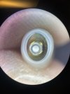
Next question. Crown is milling with open margins. In Exocad, I can see margins are open there too by .02
In crown bottoms I have protected zone near margin line set. I double checked margin placement to keep it above any undercuts below the margin.
Doesn’t seal it up. What should I change?
Here’s a pic through microscope. Looks roughly the same in exo design EE6325C7-E8F0-481C-9B02-5B9C690C8421.jpeg
 
J

Josh Claxton

Member
Full Member
Messages
25
Reaction score
0
Hanging out down here in north Flo-rida at Dynamic haha. Not really in the support role any more, been transitioning into a more R&D function.

That looks like possibly a scanning issue. If you have the protected zone near margin already set to something then it would close it, unless the scan is inaccurate. I would suggest trying an actual scan spray if you've gone the "fast actin' " route so far, the clumping on some of those is unreliable and sometime still leaves unscannable shiny areas.

Once you scan it in, just re-import it in the cad-app as a multi-die scan via add/remove mesh and you can over-ride your existing die (you will also be able to see differences to confirm that it was your scanner). After that, remark the margin and your same design will sync to the margin and you're done!

- Josh
 
RileyS

RileyS

Well-Known Member
Full Member
Messages
2,868
Reaction score
461
Hanging out down here in north Flo-rida at Dynamic haha. Not really in the support role any more, been transitioning into a more R&D function.

That looks like possibly a scanning issue. If you have the protected zone near margin already set to something then it would close it, unless the scan is inaccurate. I would suggest trying an actual scan spray if you've gone the "fast actin' " route so far, the clumping on some of those is unreliable and sometime still leaves unscannable shiny areas.

Once you scan it in, just re-import it in the cad-app as a multi-die scan via add/remove mesh and you can over-ride your existing die (you will also be able to see differences to confirm that it was your scanner). After that, remark the margin and your same design will sync to the margin and you're done!

- Josh
A little slow to the game, Pointdexter.

It turns out it was the scan.

It's probably nice not dealing with spazzes like myself all day long i bet
 
CoolHandLuke

CoolHandLuke

Idiot
Full Member
Messages
10,095
Solutions
1
Reaction score
1,411
In Exocad, I can see margins are open there too by .02
hi Riley, just seeing this now but i think it would help everyone if i can explain this publically.

you want your margin to have that thin gap of .01-.02 at the margin, the reason you want it is because the dentists who cement the crowns need to make the cement/giomer flow all the way down and seal the margin.

with no gap, you force the cement to be stuck inside the crown gap trapped by air. the margin can then absorb food and water and cause further decay. the pt could lose the tooth. that slight gap is thick enough to let the resin flow until the resin seals under the margin and solidifies.

hope this helps.
 
J

Josh Claxton

Member
Full Member
Messages
25
Reaction score
0
Sorry for the delay Riley-san 🤣 Yes though, you will notice a .02 gap in the crownbottom settings. This will be under the "additional gap" in a hidden little dropdown. Some people mistake this as the Extra cement gap from 3Shape. Big oops if they do, it's 3Shape Cement gap, the Extra CG from ol' 3 is Exo's normal cement gap you set in the colors.

That additional gap is directly set off of the prep, you'll be able to see it as if the crown bottom is floating, perfectly normal ^__^
 
RileyS

RileyS

Well-Known Member
Full Member
Messages
2,868
Reaction score
461
Next up...preserve tooth shape/convert to pontics.

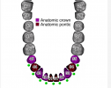
I'm designing this lower beast on a bunch of implants which the doc wants as three seperate 3 unit bridges, and a 3 unit upper. I don't want the teeth stretched around the ti bases so i did the preserve tooth shape. During the design it eventually made them stretch so crowns are going through the ti base intaglio and went through connectors step, and it also did an "anatomical wax up" and a "virtual wax up bottom" step. Why can't I understand freaking exocad?!
so what's the best way to fix all this? and how do you set this up? I think I'm going to change it to one bridge as well... pontic presesrve tooth shape.png
 
apostolis159

apostolis159

Member
Full Member
Messages
72
Reaction score
2
doc wants as three seperate 3 unit bridges
For one, how does the doc expects 3 bridges when the implants are all located in-between the teeth positions?
I don't want the teeth stretched around the ti bases so i did the preserve tooth shape. [...] and it also did an "anatomical wax up" and a "virtual wax up bottom" step.
This is the normal. When you choose to preserve the shapes and use all teeth as pontics, it basically lets you finalise the design, including the connectors, and then makes the entire design into a "digital waxup" in order to finally adapt it to the implants.
During the design it eventually made them stretch so crowns are going through the ti base intaglio and went through connectors step
It looks to me like you didn't make the connectors the proper shape, and you didn't connect all of them (as instructed for 3 bridges).
Go back to connectors (before anatomic waxup and virtual waxup bottom steps),make them the correct shapes. And do connect the ones missing (expert, right click on tooth-> connect to mesial/distal).


I'd personally set it up the same way you did (full anatomic, preserve library shape),and definitely one single bridge simply because of the implant positions.

I don't know why you got the same issue on the upper, being a single 3 unit one and implants seem positioned ok regarding to the teeth.
Can you share a webview link (make sure all meshes are visible, right click on save button, then share via dentalshare webview link)?
 
RileyS

RileyS

Well-Known Member
Full Member
Messages
2,868
Reaction score
461
For one, how does the doc expects 3 bridges when the implants are all located in-between the teeth positions?

This is the normal. When you choose to preserve the shapes and use all teeth as pontics, it basically lets you finalise the design, including the connectors, and then makes the entire design into a "digital waxup" in order to finally adapt it to the implants.

It looks to me like you didn't make the connectors the proper shape, and you didn't connect all of them (as instructed for 3 bridges).
Go back to connectors (before anatomic waxup and virtual waxup bottom steps),make them the correct shapes. And do connect the ones missing (expert, right click on tooth-> connect to mesial/distal).


I'd personally set it up the same way you did (full anatomic, preserve library shape),and definitely one single bridge simply because of the implant positions.

I don't know why you got the same issue on the upper, being a single 3 unit one and implants seem positioned ok regarding to the teeth.
Can you share a webview link (make sure all meshes are visible, right click on save button, then share via dentalshare webview link)?
You mentioned they need to be set as Pontics when setting up the case? I just did the abutment tooth of each bridge as a crown and the Pontic as Pontic but still selected the “preserve tooth shape ” for each.
 
L

LarryRDC

Active Member
Full Member
Messages
308
Reaction score
59
When designing a a wax-up digitally using pontics, Don't select "preserve tooth shape" when setting it up. It's keeping the whole pontic shape (through the interface) when generating the anatomical wax-up
 
Last edited:
apostolis159

apostolis159

Member
Full Member
Messages
72
Reaction score
2
You mentioned they need to be set as Pontics when setting up the case? I just did the abutment tooth of each bridge as a crown and the Pontic as Pontic but still selected the “preserve tooth shape ” for each.

When you choose to "preserve tooth shape", exocad treats the teeth as pontics while designing (closed bottoms). Have a look at a previous post I made here about this. My bad for phrasing wrong what I meant, sorry for the confusion. I believe you set it up correct by your description.

Here's how I'd setup this case. Basically set as anatomic implant crowns as many as the implants (6 here) in the approximately correct positions, and the rest as anatomic pontics. Connect all, simply because when implants are in-between the teeth it's almost impossible to split such a case into multiple bridges.
Screenshot 2021-12-17 194526.png 1639764214646.png

Again, I suggest you go back a few steps and connect all units (before anatomic waxup and virtual waxup bottom steps).
It should work, I believe so anyway.
I'm still on 2.4, though I don't believe 3.0 would change such a basic function. Maybe it's just an error?
 
RileyS

RileyS

Well-Known Member
Full Member
Messages
2,868
Reaction score
461
When you choose to "preserve tooth shape", exocad treats the teeth as pontics while designing (closed bottoms). Have a look at a previous post I made here about this. My bad for phrasing wrong what I meant, sorry for the confusion. I believe you set it up correct by your description.

Here's how I'd setup this case. Basically set as anatomic implant crowns as many as the implants (6 here) in the approximately correct positions, and the rest as anatomic pontics. Connect all, simply because when implants are in-between the teeth it's almost impossible to split such a case into multiple bridges.
View attachment 39963 View attachment 39964

Again, I suggest you go back a few steps and connect all units (before anatomic waxup and virtual waxup bottom steps).
It should work, I believe so anyway.
I'm still on 2.4, though I don't believe 3.0 would change such a basic function. Maybe it's just an error?
Well, after two weeks of trying to work with several other sirona connect cases that have wrecked me, trying to get printers working and trustworthy, having an employee that I can’t get consistent work from, I’ve been fighting the urge to crawl under my desk in the fetal position. So I’m so happy you’re helping so much!!!! I really feel 100 lbs lighter just from reading your post!
I’ll give it a shot in a second here.
Does your avatar indicate your a fan of dmt?
 
RileyS

RileyS

Well-Known Member
Full Member
Messages
2,868
Reaction score
461
When designing a a wax-up digitally using pontics, Don't select "preserve tooth shape" went setting it up. It's keeping the whole pontic shape (through the interface) when generating the anatomical wax-up
What I said above goes to you too Larry! Thank you!
 
RileyS

RileyS

Well-Known Member
Full Member
Messages
2,868
Reaction score
461
@sidesh0wb0b you can piss off!

Just need to vent. You’ve done nothing wrong. No offense buddy🤣
 
Top Bottom