I'll try to explain things a little bit in depth so that maybe people can better understand the problem and how things technically work.
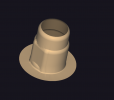
As said before the base of the ti base is set in stone and cannot be changed, it is a mesh, like your die and they are part of the folder of the manufacturer, implant system, implant platform, however the manufacturer wants to set up their implant library.
In those folders inside dentalcad/library/implant, these meshes are often called base. Scanlabs stay in STL format for compatibility with all scanners on the market.
Meshes in implant libraries come in two flavors, STL or SDFA files.
The STL one is a regular mesh that can be modified using 3rd party softwares or using exocad as I will describe below.
SDFA are meshes that are validated by exocad at the request of the manufacturer, note that they don't all do that for economic reasons, waste of their time or ego (ZZ?)
So, exocad will digitally sign the files and encrypt them in the SDFA format and then the manufacturer will distribute them on their site, or email and they'll also be available with exocad when choosing your implant library, it's top right of that window.
You can not change this file as it is signed in the config.xml file that manages the metadata and sets up the library telling where each mesh goes, where they are located in 3D space etc.
So from the top of my head I would suggest a few options, from good to ugly.
1) Verify if your milling machine has a special option dedicated for that, machines are very precise and are able to repeat a milling with more or less 10µ accuracy iirc. I know VHF has this option, probably ZZ too but I've never had to use it.
2)Try to find a way to always have the same result when modifying your pieces if it's too tight. For exemple polish with a wide wheel the vertical sides of your ti base until it fits then sandblast it. You can also sandblast your zirconia but it'll be harder to have something regular. Just don't grind arbitrarily, use a spray or something. Just don't use a hammer.
3) I haven't tested this but if and only if your base is in STL you can hack your way through, you'll need to experiment and consider where you need some gap space or light friction somewhere, for example on a C base, especially if you're going digital only.
I will give you a step thought of how to do it. These are the new bases for DESS ti bases, they've recently added new libraries that went down from 0.045 to 0.02 cement gap. Those ones are not yet validated by exocad and hence are in STL format. You can download them on their website.
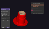
Create an offset coping case with dentaldb named "tibase", one stone only, don't worry about configs on the right you'll have access to them all in the scene. Put your base stl that you want wider in the case folder and name it "tibase.stl". Launch your case. Now you'll be able to consider the base as a die if you will and set parameters as you want.

Invert triangles if need be and close the top hole.

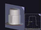
Set your margin.

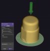
Make sure you have set the insertion direction at 90°.
You'll now have access to all the parameters necessary. Set everything to zero and uncheck prepare for milling and start experimenting. I would recommend you only play with additional spacing, unlink both radial and axial and just add positive or negative space with the radial parameter. Don't add horizontal margins as you will be doing that with your case.

When done hide everything except bottom of design and save it as an STL. Put it back in the implant folder and name it according to the base you want to modify.

Quite long and complicated, it also has its downsides like the fact that the base mesh has already been prepared for milling, so no 0.3 mm tools for example. Once you have your parameters set up it could save you some time. You can also ask someone with a very precise scanner to scan the ti base and create your bottom design from there, you'll probably have better results making that as a new base mesh.
4) The ugly ...
Dedicate a disc for those implant platforms and add a bit more percentage for the shrinkage. Keep creating a new disk with different percentage in your cam with the same disk and once you have your setting straight you're good to go. You'll have to grind your contact points though or set them lower in your exocad scene according to to the shrinkage you've added, will require maths.
Okay okay all this is too much ! Then just sandblast, polish or use a hammer ! =D


