Margin Strategy

DMC

DMC

Banned
Messages
6,378
Reaction score
260
This is not problem with your CAM or CAD.

If your margins are breaking, then look at tools.....how you are spruing.....extra material at margin settings, etc...

The Pink line is fine. No need to re-draw.


Mr. CoolLuke, just because you see some triangles does not mean you are seeing ALL the triangles.

I can change my CAM setting to have more course rendering of files to improve speed of program.

The data is still there, but not being rendered. OK?

Do not be so quick to jump to conclusions when you really do not have enough info to determine anything at all.
 
CoolHandLuke

CoolHandLuke

Idiot
Full Member
Messages
10,099
Solutions
1
Reaction score
1,411
why would you do that? i tried some freehand sculpting in several 3d suites; ive never made a tooth with more than 30 Megs of data or any kind of design that required more than 20 seconds of loading.

what do you save by not rendering the smallest detail? more importantly why does it appear that the CAM software is tracing a margin on the large triangles' edges instead of following this "nonrendered" data?

even if what you say is true you'd be saving only a second or two of rendering, and it would appear you arent saving that time at all if you have to remill or remake your product.
 
DMC

DMC

Banned
Messages
6,378
Reaction score
260
What do you mean, "If it is true? "

Yes this exists in most all cam software on the planet. Try nesting 40 files and the cad for the fixture and other equipment along with the cad of the spindle and tools.......now you have a screen full of millions of triangles.

Ok?

CAM software engineers decided this was a necessary parameter for their software.
 
Last edited:
rkm rdt

rkm rdt

Well-Known Member
Full Member
Messages
21,458
Reaction score
3,288
to All of you who are glad to have *** back, do you condone calling anyone on DLN an idiot?

Do you find this amusing or as some of you call it a " sense of humour" ?

I don't . There is no room for this on here and I call on the administrators to curb this once and for all.

I would like to read posts that I can learn from without the ad hominem attacks. No one deserves that especially someone like Luke who contributes so much to this site.

Or we could just let it go as just " Scotty being Scotty". If that is the case then DLN has just lowered the bar to idiot status.
 
CoolHandLuke

CoolHandLuke

Idiot
Full Member
Messages
10,099
Solutions
1
Reaction score
1,411
right... so this cam software that magically saves time by not rendering small data, still calculates cam on non rendered polygons while maintaining an extra set of data on the screen that may have 75% of the rendering.

essentially you are telling me the data is loaded twice, calculated on invisible data, and saves time.

does not compute.

last time i was fed this false info was from Laserdenta trying to tell me the software closes holes in the scan by using scanned data that was discarded, the software wasnt just creating closed holes by using an average of the point plane.

we both know that isnt what is going on.

there is no such thing as INVISIBLE DATA.

when you decimate a mesh you ELIMINATE minor data and you can't get it back without reverting to a previous save file.

try decimating and un-decimating in a program like zBrush. that's about the only program i've seen that will let you do it. no CAM i've ever known will even defeature a mesh. but if you can show us all your slider that makes triangle size big and small and back again i'll eat my words. gladly.
 
CoolHandLuke

CoolHandLuke

Idiot
Full Member
Messages
10,099
Solutions
1
Reaction score
1,411
to All of you who are glad to have *** back, do you condone calling anyone on DLN an idiot?

Do you find this amusing or as some of you call it a " sense of humour" ?

I don't . There is no room for this on here and I call on the administrators to curb this once and for all.

I would like to read posts that I can learn from without the ad hominem attacks. No one deserves that especially someone like Luke who contributes so much to this site.

Or we could just let it go as just " Scotty being Scotty". If that is the case then DLN has just lowered the bar to idiot status.

dude, don't even worry about it. Idiot is a term of endearment. he can't openly say what he thinks of me because it would be too hard to accept for most people.

they are only words at the end of the day.
 
rkm rdt

rkm rdt

Well-Known Member
Full Member
Messages
21,458
Reaction score
3,288
dude, don't even worry about it. Idiot is a term of endearment. he can't openly say what he thinks of me because it would be too hard to accept for most people.

they are only words at the end of the day.

I'm not worried about you. You can handle yourself quite well.

I'm addressing the Scotty lovers on here that condone this .
 
Travis

Travis

Nothing to see here
Staff member
Messages
7,224
Reaction score
323
Keep this on track or it will be closed. Stop the name calling and keep it civil.
 
CoolHandLuke

CoolHandLuke

Idiot
Full Member
Messages
10,099
Solutions
1
Reaction score
1,411
can you do it backwards now ? can you get back to the previous level of detail ?
 
DMC

DMC

Banned
Messages
6,378
Reaction score
260
right... so this cam software that magically saves time by not rendering small data, still calculates cam on non rendered polygons while maintaining an extra set of data on the screen that may have 75% of the rendering.

essentially you are telling me the data is loaded twice, calculated on invisible data, and saves time.

does not compute.

last time i was fed this false info was from Laserdenta trying to tell me the software closes holes in the scan by using scanned data that was discarded, the software wasnt just creating closed holes by using an average of the point plane.

we both know that isnt what is going on.

there is no such thing as INVISIBLE DATA.

when you decimate a mesh you ELIMINATE minor data and you can't get it back without reverting to a previous save file.

try decimating and un-decimating in a program like zBrush. that's about the only program i've seen that will let you do it. no CAM i've ever known will even defeature a mesh. but if you can show us all your slider that makes triangle size big and small and back again i'll eat my words. gladly.


No, there is invisiable data Luke.

More data can exist than what is rendered! OK?

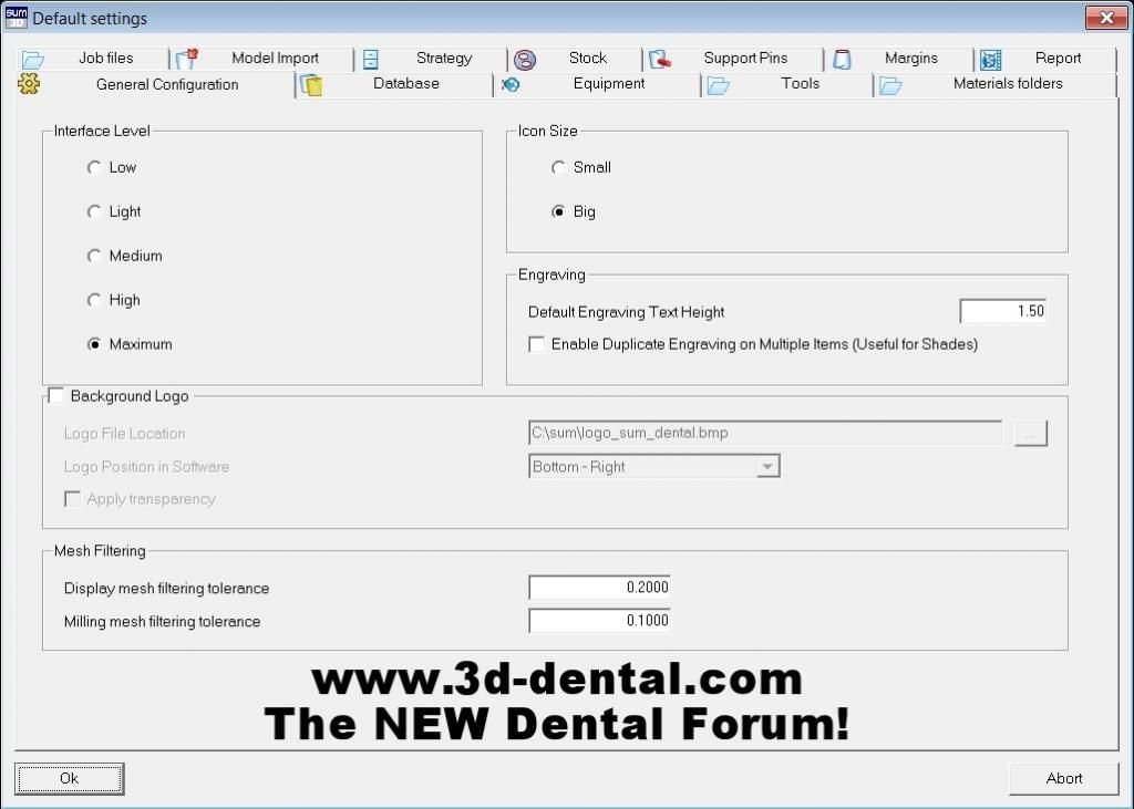
See above screen-shot please.... You are not speaking from experience or knowledge.

Just spouting off non-sense again and guessing.

Yes, there can be more data than what is rendered, and this data is not lost.

It is absolutely used to produce the finished CAM file, but is not shown on the screen.

I know exactly what I am talking about.

There is similar parameters in some CAD programs as well.

I think CAM is too complicated of a subject, and you have too little experience with it to be posting answers/help in any CAM related question on this forum.

Thank you for your understanding.
 
DMC

DMC

Banned
Messages
6,378
Reaction score
260
Well, I just showed you the place where we can choose the rendering.

This is separate from actual milling tolerance.

And, both of those are separate from the mesh reduction function on importing a file, like what CADFAN has shown.

Three different functions of reducing meshs, all for different reasons.

I have spent weeks with the engineers who did this Luke.

Why are you even trying to argue with me?

There it is!!! Right above! You still cannot believe it huh?

OK, then you truly are an ixxxt then. What else can I say?? :rolleyes:
 
CoolHandLuke

CoolHandLuke

Idiot
Full Member
Messages
10,099
Solutions
1
Reaction score
1,411
you have it set to display a normal mesh filtered to .2mm

then you have it set to re-filter that same normal mesh back to 0.1mm

then at time of milling the same normal mesh is again refiltered however you configured that.

and you are telling me this is for the purposes of saving time?

bonkers.
 
DMC

DMC

Banned
Messages
6,378
Reaction score
260
One value is for only rendering. Has no effect on actual milling, or the milling path created.

The other is for the actual milling tolerance. Kinda like a minimum limit of distance between Two coordinates that link to make a tool-path. (Connect the Dots)

Prevents too many coordinates and too long of a program for some mills to run. Why have <5um distance between coordinates if your mill only has >10um mechanical resolution?

Two different things that have nothing to do with each other Luke.

Just like I stated from the very beginning. What you see, is not always what you get and not always what actually exists.
 
Last edited:
MikeW

MikeW

Member
Full Member
Messages
62
Reaction score
12
One value is for only rendering. Has no effect on actual milling, or the milling path created.

The other is for the actual milling tolerance. Kinda like a minimum limit of distance between Two coordinates that link to make a tool-path. (Connect the Dots)

Prevents too many coordinates and too long of a program for some mills to run. Why have <5um distance between coordinates if your mill only has >10um mechanical resolution?

Two different things that have nothing to do with each other Luke.

Just like I stated from the very beginning. What you see, is not always what you get and not always what actually exists.

While this is true, I would refrain from changing the Milling mesh filtering tolerance.

For most all to understand, imagine that when you import a crown there are not just one crown, but two.

As Scott mentioned above, one is the one you see which can be degraded in visual quality because its only visual data for the user to see.
This really only helps the more units you import. As he stated, the more triangles, the slower the image rotates and you can even notice a drop in FPS during these rotations / panning depending on your PC.

The 2nd "crown" is the one that the CAM sees during calculation and that it executes it's operations against and what is actually milled on the machine. Changing the milling mesh filtering tolerance is degrading the surface quality of the restoration which WILL affect the milling result. What may have been a smooth facet, may develope some more rough attributes. The machine WILL mill out these inaccuracies because that's what it's basing it's operations on.

The "connect the dots" analogy would be better related to the "minimum point distance" parameter that is under General Parameters. This is the distance that the CAM will use as a minimum value for rendering toolpaths. Naturally, the higher this value is, the less detailed a toolpath you'll get.

here is an example of a toolpath generated with the value set to 0 which allows SUM to determine what is needed to machine the surface:

In this case it was 0.0547mm

05.jpg
05 toolpath.jpg


Now here is the same toolpath but with a 0.0447mm minimum point distance:

04.jpg

04 toolpath.jpg

For some reason, it appears that manually changing the value doesn't do anything on my SUM - I'll have to check with the home office to see if this is intended for Dental.
Instead to increase the accuracy, I had to go from "Normal" to "Superfinishing" under the "Machining Accuracy".
 
Last edited:
Top Bottom