Hybrid Custom Abutments/Screw Retained Crowns on a VHF Mini?

cdlab

cdlab

Member
Sponsors
Messages
39
Reaction score
1
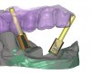
I have been having some issues with my mill (VHF Mini) not milling out the abutment fit properly for my hybrid screw retained crowns and custom abutments...

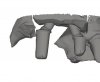
Some cases the abutment slides right onto the ti base, and other cases (different case, but same exact 3shape library file, same platform, etc) the abutment is a full millimeter off (it is way too small for the ti base to fit into).

Design is with 3shape, some cases mill out perfectly, and some don't fit at all! I measured in 3rd party cad software both the abutment files that mill out correctly, and those that don't...all of them measure exactly the same (correct dimensions for the ti base to fit in...3 mm).

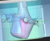
So in digital space, the dimensions are perfect for a 3mm ti base to fit for all the stl files, after milling, the dimensions are in some cases perfect at around 3mm, but other cases are 2.4mm.

Anyone else milling abutments with a mini? Any advice? Within the CAM software there is an abutment option, also 4/5 axis finishing with priority on the Cavity, also an option to increase the abutment fit by anywhere from .01 to .25 mm (oversize of abutment fit)....still no good!

Any advice or insight would be greatly appreciated.

(more info: all digital, model-less workflow, trios scan -> 3shape w/Glidewell library 4.5mm ti base -> stl fit is perfect in cad (measured both digi library file and stl output from dental designer) -> milled fit is sometimes perfect, but sometimes a full 1mm off!)
 
DMC

DMC

Banned
Messages
6,378
Reaction score
260
Zr shrinkage is wrong in CAM?

Forgot to add the expansion percentage during importing of that file into the CAM?

What CAM....you never mentioned that.
 
Terry Whitty

Terry Whitty

Well-Known Member
Full Member
Messages
559
Reaction score
136
That's the first thing i would check too..sounds like the culprit, especially if its too small all over... Is that the case for the ones that don't fit?

If you want 3mm but are ending up with 2.4 then thats 20% less...so have a look at the expansion percentage of milling as it points to that.
 
cdlab

cdlab

Member
Sponsors
Messages
39
Reaction score
1
Thanks for the replies. It is not a shrinkage issue. I am using the default CAM software that VHF provides with their Mini (in this case, the mini is an EZ Mill 400+ and the CAM is CB Dental CAM).

Any other options?
 
B

bigbrush

Active Member
Full Member
Messages
153
Reaction score
34
Hi Jordan,

are you shure choosen Abutment before placing. The other options are crown fullanatomic. Then choose 4/5 axis possible and don`t turn the abutment when placing it, only move. Otherwise the whole isnst in your wholeaxle. Hope this helps.
 
cadfan

cadfan

Well-Known Member
Full Member
Messages
1,524
Reaction score
207
Do you have the problem with angled abutments , inside and outside have very different angles , mill strategie, nesting priority the software isnt very intelligent

if you have next time such a problem upload the file ill make a simulation with sum.
 
Last edited:
cdlab

cdlab

Member
Sponsors
Messages
39
Reaction score
1
Hi Jordan,

are you shure choosen Abutment before placing. The other options are crown fullanatomic. Then choose 4/5 axis possible and don`t turn the abutment when placing it, only move. Otherwise the whole isnst in your wholeaxle. Hope this helps.

I am sure that I have the type set to abutment, and tested with and without 4/5 axis with cavity priority. I have most likely been turning the abutment after placing into cam...so this is a possible lead! Thanks, I will test without rotating the abutment...sounds weird but I have had weirder problems with this CAM before. Can you please explain what you mean by "Otherwise the whole isnst in your wholeaxle".

Do you have the problem with angled abutments , inside and outside have very different angles , mill strategie, nesting priority the software isnt very intelligent

I was thinking that the software might be at fault here...with no fix available. I hope that is not the case and that I am able to find a solution soon...
 
cadfan

cadfan

Well-Known Member
Full Member
Messages
1,524
Reaction score
207
The problem is the software has no simulation so you cant see non milled areas if you have the same problem next time upload the file and maybe an empty blanck 98 mm with enlargement factor and your router assignment ill create a cam file for you if you want or only a simulation.Below its an example but dont mill it your router assignment is maybe not the same but the software can read it just switch to external cam and than file read in you see the software creating the file and although the used burs but dont start it !!!!!!!!!!!!!!!!!!!!!!!!!!


https://www.dropbox.com/s/n742d29sasy30zx/zrt14_Transpa1_2013-12-09_13-25-27.VHF
 
Last edited:
B

bigbrush

Active Member
Full Member
Messages
153
Reaction score
34
Hello Jordan,
I try to explain, but it is a little bit difficult. the mill has 10° + and - movement on the A -achsle, your Screewhole has to been inside of this movement otherwise it won`t be milled out complet. So if you have havy a angled crown you might become a problem. The VHF Software has no preview of the milled object, but if you see red sparkles on you blue object when it is positioned this will not be reached.
If you take the DS Software by wieland you can handle som of these problems very well ( so I do ).
The new VHF software does a better analising of the STL and mills 4 ax- simultan, I had some really good results with it. Keep an eye on your angles while construction in your cad SW, this helps also.

Tom
 
cadfan

cadfan

Well-Known Member
Full Member
Messages
1,524
Reaction score
207
Below a picture the jaw surgery was sorry for that but you can handle it with sum the problems are more the non touched ti interfaces second pic just for fun as a full zi abutment with your standard software you can handle maybe half off these angles. Third the abutments with ti interface. Its part of the algorithm mill versus. nesting and their are some real stupid programs outside.
 

Attachments

  • Limit.jpg
    Limit.jpg
    34.7 KB · Views: 43
  • Abautment over angled.jpg
    Abautment over angled.jpg
    47.6 KB · Views: 39
  • Abutment.jpg
    Abutment.jpg
    20.7 KB · Views: 37
Last edited:
NicelyMKV

NicelyMKV

Well-Known Member
Full Member
Messages
3,557
Reaction score
262
Didn't select wax or something by mistake in the CAM did you?


Sent from my iPad using Tapatalk HD
 
cdlab

cdlab

Member
Sponsors
Messages
39
Reaction score
1
I attempted to mill again without rotating the abutment. Still same result...abutment cavity way too small, ti base wont fit in.

Hello Jordan,
I try to explain, but it is a little bit difficult. the mill has 10° + and - movement on the A -achsle, your Screewhole has to been inside of this movement otherwise it won`t be milled out complet. So if you have havy a angled crown you might become a problem. The VHF Software has no preview of the milled object, but if you see red sparkles on you blue object when it is positioned this will not be reached.
If you take the DS Software by wieland you can handle som of these problems very well ( so I do ).
The new VHF software does a better analising of the STL and mills 4 ax- simultan, I had some really good results with it. Keep an eye on your angles while construction in your cad SW, this helps also.

Tom

The abutments/Screw Retained Crowns that I am milling are actually not angled at all. I have not yet attempted an abutment that was angled more than a couple degrees off...haven't had the chance yet.

I will look into the wieland software.

Didn't select wax or something by mistake in the CAM did you?


Sent from my iPad using Tapatalk HD

Nope...
 
cdlab

cdlab

Member
Sponsors
Messages
39
Reaction score
1
the DS Software by wieland you can handle som of these problems very well ( so I do ).
The new VHF software does a better analising of the STL and mills 4 ax- simultan, I had some really good results with it. Keep an eye on your angles while construction in your cad SW, this helps also.

Tom

Where can I get my hands on either the DS software, or the newer VHF cam software?

Thanks!
 
zero_zero

zero_zero

Well-Known Member
Full Member
Messages
6,303
Reaction score
1,397
Go to your implant library, find the STL file which serves as the negative of the Ti insert ( called base or something like that )... open it with a 3D editor like Rhino or FreeCAD...scale it up a bit while keeping the same reference coordinates ( center/bottom is usually in zero )... it might take a few tries till you nail it... Don't forget to backup the original file. ..
 
cdlab

cdlab

Member
Sponsors
Messages
39
Reaction score
1
Go to your implant library, find the STL file which serves as the negative of the Ti insert ( called base or something like that )... open it with a 3D editor like Rhino or FreeCAD...scale it up a bit while keeping the same reference coordinates ( center/bottom is usually in zero )... it might take a few tries till you nail it... Don't forget to backup the original file. ..

The problem is that for some cases I don't have an issue at all...ti base fits perfectly, and other cases, same exact library and platform size, same exact base file....different results after milling. So I could do this but my procedure would be: 1) mill out case, if ti base doesn't insert properly, blow up base file size, rebuild 3shape library, switch implant, remill...seems like there has to be a better solution, and at this point I am starting to wonder if I need a better mill, or just better cam software.
 
zero_zero

zero_zero

Well-Known Member
Full Member
Messages
6,303
Reaction score
1,397
Could it be CAM issue ? Save a few STLs of the same interface type...then compare the inside geometry ( with Meshlab or similar software ) of a good fitting vs. a poor fitting one...if is the same then is the CAM doing something wrong...
 
cdlab

cdlab

Member
Sponsors
Messages
39
Reaction score
1
Could it be CAM issue ? Save a few STLs of the same interface type...then compare the inside geometry ( with Meshlab or similar software ) of a good fitting vs. a poor fitting one...if is the same then is the CAM doing something wrong...

Yeah I have measured multiple STLs in Meshlab. They are all the correct dimensions, then when they mill out, some mill out properly and some don't...
 
cadfan

cadfan

Well-Known Member
Full Member
Messages
1,524
Reaction score
207
If anybody wants to buy a new software ask '*** for a 30 days trial of sum for the mini in my opinion its the best the DS has to much limits but try it too 60 days trial available sum trial is free DS for the dongle maybe 150
 
B

bigbrush

Active Member
Full Member
Messages
153
Reaction score
34
Hello cadlab,

the DS software for the mini is only sold by wieland, at the moment. For the new VHF cam you should ask your local dealer.
 
cdlab

cdlab

Member
Sponsors
Messages
39
Reaction score
1
If anybody wants to buy a new software ask '*** for a 30 days trial of sum for the mini in my opinion its the best the DS has to much limits but try it too 60 days trial available sum trial is free DS for the dongle maybe 150

I was told by a reputable company that SUM 3D is not yet available for use with the VHF Minis....are you sure?
 
Top Bottom